Modification of Harbor
Freight Centec handheld metal detector Cen-tech #97245
Some quick mods of the ‘pinpointer’:
·
Add
radioshack vibrate motor
·
Add
switch selector for original piezo buzzer or vibrator
·
LED
straightened and brought out top of case
o
LED
now lights when metal detected and not a ‘flashlight’ anymore.
o
Sink
the LED with a 1k resistor versus the oem 300 ohms
o
Current
draw with no detect is < 5ma now (no LED lit)
o
With
piezo selected (and LED lit), current draw is ~45ma
o
With
vibrator motor (and LED lit) current draw is about 38ma
·
Add
external adjustment for the internal balance potentiometer
·
Add
larger knobs for the sensitivity adjustment and external adjustment
Click here for effect of temperature
on the pinpointer
Given the schematic diagram from here
(A super BIG thank you to whoever provided the original!!!):
With the mods and additions
shown here:

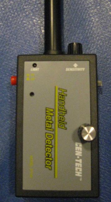
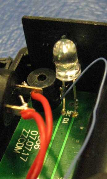
The case outside,
notice the LED now shines through just above the ‘Light’ label.
The added
knob on the oem sensitivity and
the new external adjust.
The slide
switch for piezo or vibrator select on the right.
Replaced the
oem pushbutton switch on the
left.
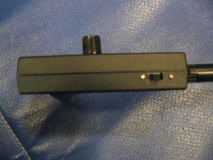
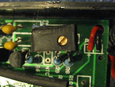
Side view showing the
added vibrate motor/piezo selector switch. I have a micromill so cutting the slot was easy.
There is enough lower part of the case above
the PCB to fit the switch
Up-close on the switch,
can also see the 1k resistor for the led from the schematic above.
The cut for the jumper
shown on the schematic is a solder blob as shipped between the two feedthroughs just below ‘BZ’ seen below.
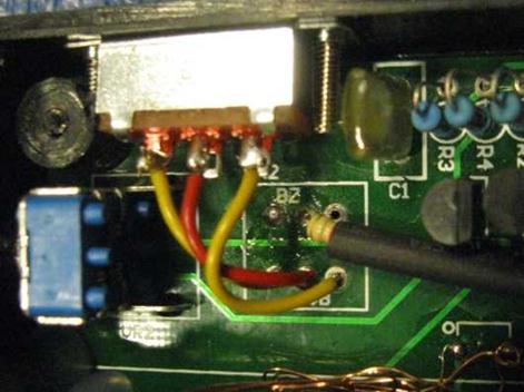
The buzzer
add, also showing R14 for the 220 ohm resistor (just left of the coiled red
wire)
There is already a
place on the PCB to mount the buzzer motor. I coiled the wire because I never
cut if not required J
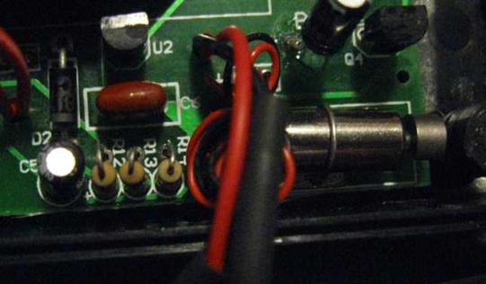
Showing left LED leg
cut and LED straightened to bring out top of case. Wire runs over to the 1k resistor
in the switch section above.
Adding external control for the
internal potentiometer.
This device is extremely affected by
temperature.
The NTC thermistor shown in the
schematic, but absent from the device, is really needed, or else something to
compensate for temperature changes is required. The internal potentiometer
provides this capability if the pot is brought out external to the case so you
can tweak as required to obtain the max distance, or
at least the same distance across temperature.
The nub end of the
external adjustment knob, adding the black rectangle ‘washer’ allows a force
fit of nub end into the potentiometer adjustment slot when the case is screwed
together

The internal
potentiometer, with a captive adapter to hold the nub end in the slot so cannot
shift side to side.
Measuring temperature dependency
Using a handheld
non-contact thermometer aimed at the case (much better would be at the PCB!!)
Setting sensitivity and
new external adjust to ‘max’ at room temperature (69F)
|
Temperature |
Detect
distance |
|
69F |
1.875
inch |
|
55F |
0.75
inch |
|
41F |
0.50
inch |
|
12F |
0.25
inch |
With the initial
adjustment of external to ‘max’ at room temperature, temperatures above 70F
just ‘detect’ continuously,
the external adjust must be ‘adjusted’
for new higher temperature if you want max range.
Copyright (all but schematic) astrogene1000@2012
Copyright schematic original author